Install and use the FRAM chip add-on for the multi-24 controller module
The multi-24 can store its internal Modbus holding register values up to 10 000 times. While this is plenty for storing setpoint values in most applications, when pulse meter values or runtime counters need to be stored, 10 000 saves can be soon exhausted (e.g. 10 000 hours ≈ 14 months). Here, the additional FRAM chip can be used. This chip can be written to like RAM without any limitations.
The 250 16-bit FRAM chip Modbus holding registers are mapped to registers 2000..2249. These registers can be read and written normally and are saved immediately, so there is no need to call the SaveRegistersF function.
The chip is slid onto the connector on the multi-24 PCB as it is in the following photos: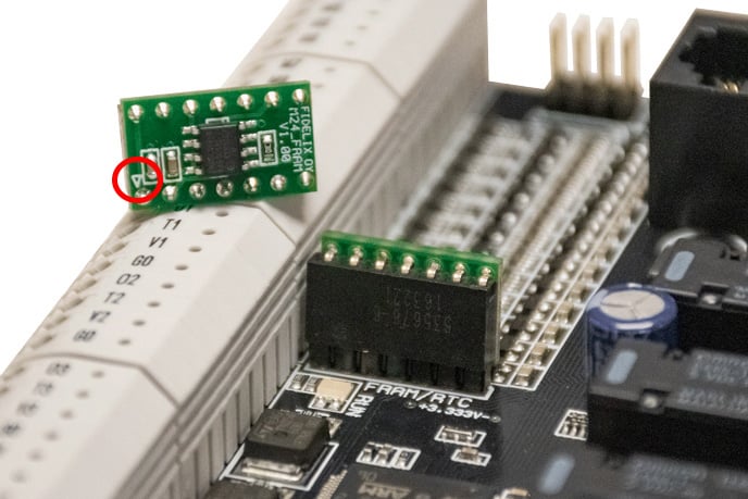
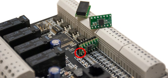 Make sure the little white triangle (inside the red circles on the photos) is facing downwards!
Once installed, when powering up, the multi24 controller module's RUN LED (right next to the chip) will blink fast three times, indicating the successful discovery of the FRAM chip.
To read or write to the registers on the FRAM chip, simply use the normal firmware functions SetRegisterF, GetregisterF, GetLongRegisterF, and SetLongRegisterF with register numbers 2000..2249 like this:
INT_ReturnValue := SetRegisterF (RegNumber := 2003, Value := 4783);
    (where RegNumber gets a UINT, and Value a WORD value variable)
INT_ReturnValue := GetLongRegisterF (RegNumber := 2075);
    (where RegNumber gets a UINT value variable)